Home/Products/Wedge Wire/Wedge Wire Screen Laterals
Wedge Wire Screen Laterals
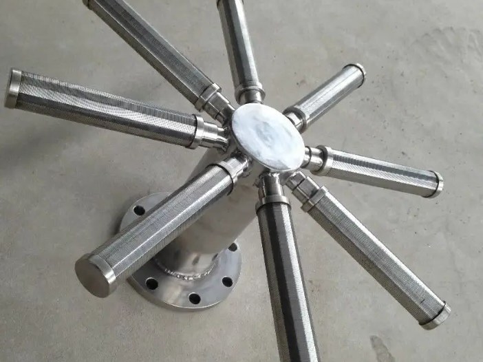
Wedge wire laterals: the branch pipes inside a vessel or well that collect or distribute flow through a fixed slot. Open area is set by slot and wire, not by drilling, so it stays constant over the life of the bed.
Wedge Wire Screen Laterals
Wedge wire laterals: the branch pipes inside a vessel or well that collect or distribute flow through a fixed slot. Open area is set by slot and wire, not by drilling, so it stays constant over the life of the bed.
| Material | 304 / 316L stainless steel, 2205 duplex on request |
|---|---|
| Size range | OD 25-100 mm, slot 0.10-2.0 mm, length up to 3000 mm; threaded, flanged or weld-end connections |
| Typical application | Resin and carbon traps, ion exchange vessels, sand filters, wellpoint dewatering, desalination intakes |
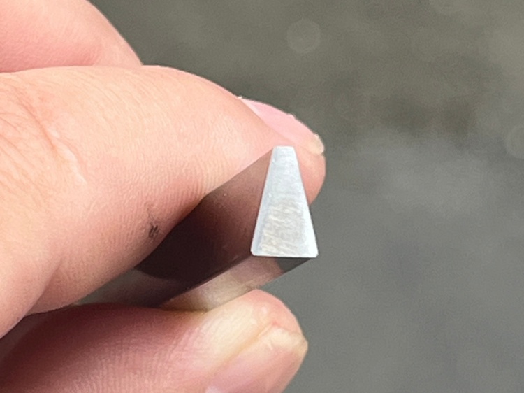
| Cross-section | Square — also drawn to your drawing |
| Surface | Bright drawn, as required |
| Packing | Coil, spool or straight length |
A lateral is the branch pipe inside a vessel or a well: flow leaves or enters the bed through its wall, and the slot in that wall is the only thing standing between the media and the process line. Perforated pipe and mesh-covered pipe both start with a fixed hole count and lose it to wear, corrosion or media migration. A wedge wire lateral does not: the slot is formed by a V-profile wire wound on support bars, so its width is set by the wire section and it holds that width as the lateral wears.
What a lateral is asked to do
Hold media, pass liquid. Resin, activated carbon, sand and ion exchange beads all sit on top of the lateral. The slot must be narrow enough that the finest fraction cannot pass, and wide enough that the pressure drop stays low. Those two requirements meet at a slot around 0.2–0.5 mm for most resin and sand beds.
Distribute flow evenly. In a vessel with several laterals on a header, flow takes the path of least resistance. Laterals sized for the same open area and the same length behave the same way; one long lateral and three short ones do not. The header and lateral layout matters as much as the slot.
Survive backwash. Backwash reverses the flow and pushes the bed against the lateral at several times the service velocity. That is where a mesh-covered screen fails first — the mesh tears at a support point — and where a welded V-wire lateral, with no mesh to tear, keeps its slot.
Come out for media change. Resin has a life; laterals outlive it. Threaded or flanged connections let a lateral be unscrewed and pulled without cutting the header.
The three dimensions that decide a lateral
Diameter sets the flow area behind the slot. A 50 mm OD lateral handles roughly four times the flow of a 25 mm one at the same velocity, which is why laterals are usually sized on velocity rather than on slot area alone.
Slot sets what is retained. Round slots are impossible in this construction — the slot is the gap between two V wires, and its width is measured across the outside face. Two adjacent wires form a slot that widens inward, so a particle that starts through cannot wedge.
Length and connection set how it mounts. Up to 3 m in one piece is normal; longer runs use a threaded coupling or a welded joint. Blind end caps are standard — the last 50–100 mm of a lateral carries no slot, so media cannot enter at the tip.
Laterals vs panels vs candles
All three are wedge wire; they differ in shape and in how flow is arranged. Panels are flat and used as decks — see wedge wire screen panel. Candles are closed cylinders with one outlet, used where flow comes from all sides into a single port. Laterals are open-ended branch pipes on a header, used where flow must be spread across a vessel floor or a well screen interval.
If the application is a well rather than a vessel, the geometry is closer to a screen — water well screens vs slotted pipe covers that comparison.
Specifications
| Outside diameter | 25–100 mm |
|---|---|
| Slot | 0.10–2.0 mm, measured across the outside face |
| Length | Up to 3000 mm per piece |
| Profile wire | V-profile, typically 1.5×2.5 mm to 3×5 mm |
| Support bars | 3–8 mm, spacing set by pressure drop and backwash load |
| Connection | Threaded (BSP/NPT), flanged, or weld end; blind cap standard |
| Material | 304 / 316L stainless; 2205 duplex on request |
| Surface | Pickled and passivated, or bright as welded |
Slot sizing follows the same arithmetic as any screen — how to calculate slot size walks through it. The support bars behind the wire are covered on the support bar page. Send the vessel drawing, the media size and the flow rate — lateral count and slot follow from those three.
Related products
Ready to start your project?
Send us your drawing or sample — we reply within 24 hours on working days.